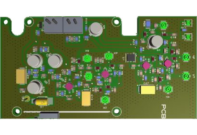
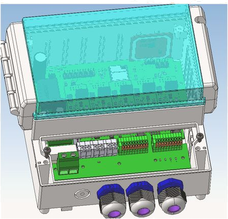
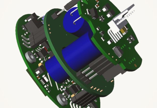
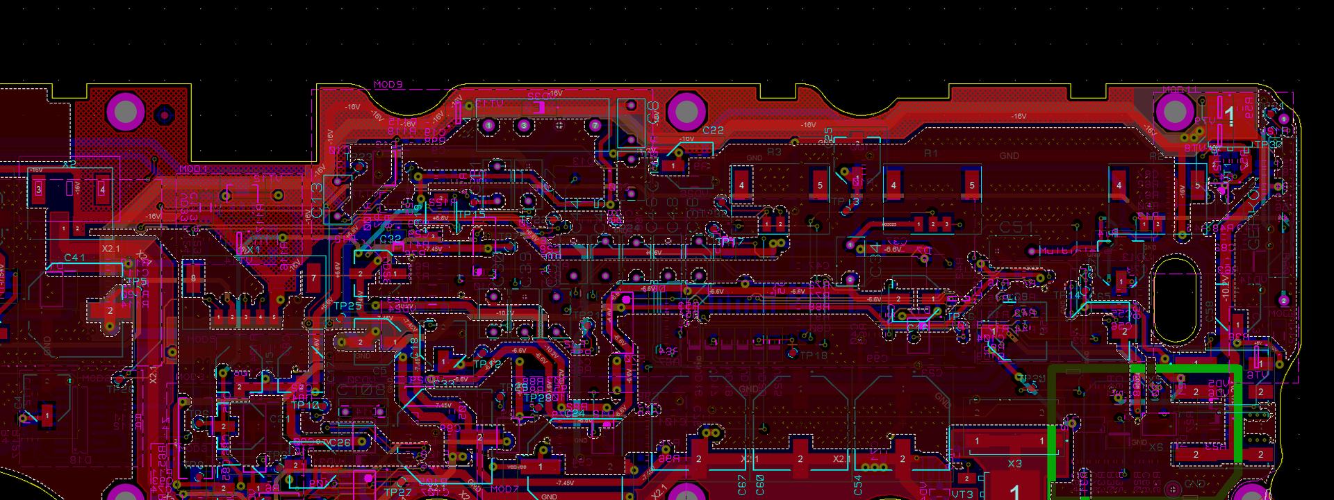
Engineer at a monitor with a 3D model of a product in CAD

MPV-LAB · engineering office

IoT device development: board, firmware, radio

The lead engineer is accountable for the result.

An AI team speeds up the work — you get your device faster and cheaper than an in-house department.

SchematicsPCBfirmwareproduction ramp-up20+ years of practice

STM32 · ESP32Nordic nRF52 · nRF53Zephyr RTOSBLE 5.x · MatterKiCad · ProteusModbus · CANLoRaWANEdge AISCADAmachine vision

Layer 1 · Enclosure

The customer sees the enclosure. We see everything under it.

Layer 2 · Board

The board decides whether the instrument works at all.

Layer 3 · Traces

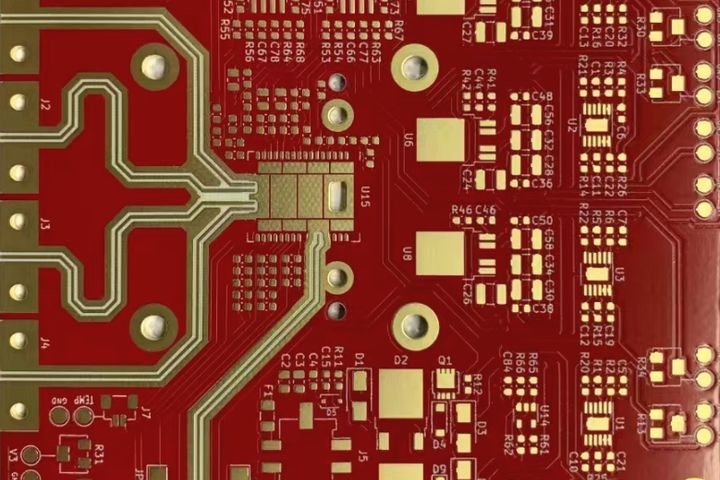
Every trace has a length, an impedance, and a cost of getting it wrong.

Layer 4 · Silicon

Register by register. Clock by clock.

MPV-LAB · Turnkey development

IoT devices and firmware, finished all the way

Board, firmware, and radio in one contract, through to the pilot run. A lead engineer and his AI team, mechanical designer, programmer, and reviewer, carry the project from the first call to working hardware on the bench.

Services

What does MPV-LAB actually do?

MPV-LAB develops connected devices end to end: board, firmware, and radio under one contract, plus schematics and PCB, microcontroller firmware, RF front end and antennas, operator HMI, industrial automation, and production readiness. The client gets finished hardware plus the complete source package, instead of a set of separate vendors to coordinate on their own.

01

Robotics, industrial edge AI, and machine vision

industrial PLCsSCADAModbus · CANTCP / UDPSIMPLE-SCADAroboticsEdge AI · TinyMLTFLite Microsensor fusionCV + AI

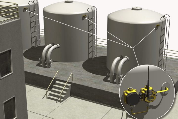
A complete cell: explosion-proof field sensors, a radio link to the control room, controllers, and integration with the plant systems already in place. A separate line of work is machine vision with recognition, where a camera replaces manual inspection. Inference runs on the device itself: TensorFlow Lite Micro models on the controller or an edge module, so the line keeps working when the network does not. Robotic cells and sensor fusion sit in the same scope. All of it has run in a real plant, not only on a bench.

Tank farm with wireless level sensors and a radio link to the control room

Robotics & vision → · Edge AI / TinyML →

02

Schematics and printed circuit board

KiCadProteus 8–9Qucs-S4–8 layerscontrolled impedancelow-power designDFM3D enclosure fit

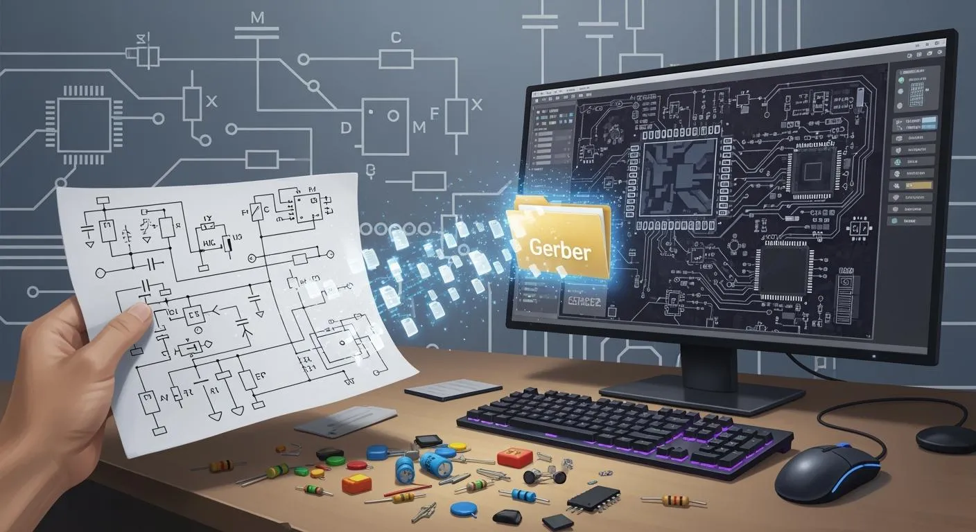
Schematic design, part selection with availability and cost in mind, multilayer layout, power and signal integrity. The output is Gerber, Excellon, a BOM, and an assembly file that a fab accepts without questions. Enclosure and mounting are checked in a 3D model in Kompas3D or SOLIDWORKS before boards are ordered, so board and housing meet without a file in hand. Battery products are budgeted at the microamp level before layout: sleep current, wake rate, and radio duty cycle decide the cell size, not the other way round. Every board passes a DFM review with the fab before release.

Close-up of an RF board with matched lines and gold-plated pads
03

Firmware and embedded software

STM32ESP32Atmel · MicrochipTexas InstrumentsZephyr RTOSFreeRTOSNordic nRF52 · nRF53BLE 5.xMatter · Threadsecure bootsigned OTAMISRA-Cunit tests · CIC / C++PlatformIO

Code written to automotive rules: no hidden lockups, deterministic response time, and explicit fault handling. Peripheral drivers, communication protocols, over-the-air updates, and logging that supports field failure analysis. Connected products run on Zephyr RTOS with Nordic nRF52 and nRF53 silicon, BLE 5.x, and Matter over Thread. Update images are signed and checked by secure boot, so an over-the-air update cannot install foreign code. Code follows MISRA-C rules, carries unit tests, and is built by CI on every commit. A particular strength is distributed multiprocessor systems, where several controllers split the work and must stay in sync without losing data.

Screen showing firmware source code in a dark editor

Firmware services →

04

RF front ends, antennas, radar

LoRaWANBLEZigBee6LoWPANFMCW 5.8 GHz4D imaging radarsensor fusionFCC / CE pre-compliancepatch arrays

Impedance matching, link budget calculation, patch antennas and arrays on FR-4, and radar modules with FPGA-side processing. Numbers first, then measurements on real hardware, instead of tuning after the fact. For IoT the radio is chosen on range and power draw, not on fashion. Work also covers 4D imaging radar and fusion of radar data with camera or inertial input. Pre-compliance measurements for FCC and CE are taken in-house before the product reaches a certification lab, so the first formal test is not the first measurement.

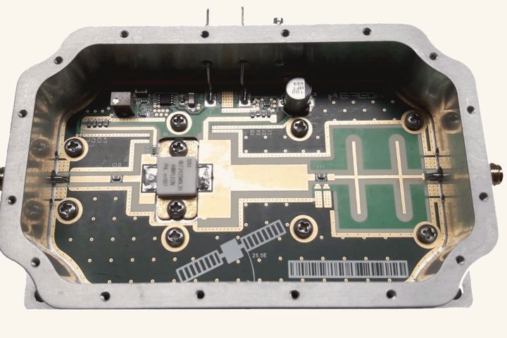
Power amplifier board inside a milled aluminium housing with RF connectors

RF & radar services → · Wireless / IoT →

05

Production ramp-up

pilot runQC test fixturedocumentationproduction support

A pilot run, a factory test fixture that returns a plain pass or fail, a documentation set, and support through the first build at a contract manufacturer. The product ships to the plant with instructions on how to test it, shielding frames and RF acceptance included.

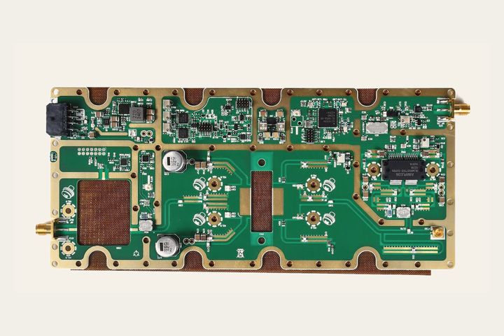
Assembled RF board in a gold-plated shielding frame with RF connectors
06

On-device operator HMI

DWIN DGUSWinstar GUI BuilderTFT · OLEDresistive touch

Instrument screens are drawn for a gloved hand on a plant floor, not for a pretty screenshot. Off-the-shelf DWIN DGUS and Winstar panels take load off the main controller, and custom display graphics are written where a panel is not enough.
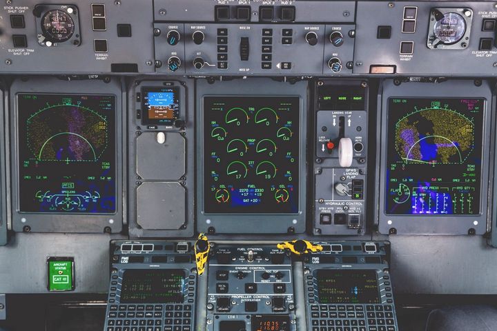
Instrument panel with backlit screens and controls

Stack

The tools behind it

The list below is a working toolkit, not a showcase: every line stands behind a finished product that was built, debugged, and delivered. If the line you need is missing, saying so up front beats learning it on your budget.

Controllers

  • STM32
  • ESP32
  • Nordic nRF52
  • Nordic nRF53
  • ARM Cortex-M
  • Atmel AVR
  • Microchip PIC
  • Texas Instruments
  • industrial PLCs

Languages and toolchains

  • C
  • C++
  • Python
  • Zephyr RTOS
  • FreeRTOS
  • bare metal
  • PlatformIO
  • nRF Connect SDK
  • VS Code
  • MPLAB
  • Arduino

Debug interfaces

  • SWD
  • JTAG
  • UPDI
  • PDI
  • SPI
  • I2C
  • I2S
  • UART

Communication protocols

  • Modbus
  • CAN
  • TCP
  • UDP
  • USART
  • reverse engineering of proprietary protocols

Radio links

  • LoRaWAN
  • BLE 5.x
  • Matter
  • Thread
  • ZigBee
  • 6LoWPAN
  • Sub-1GHz
  • FMCW radar
  • 4D imaging radar

Design tools

  • KiCad EDA
  • Proteus 8–9
  • Qucs-S
  • Kompas3D
  • SOLIDWORKS
  • DWIN DGUS
  • Winstar GUI Builder

Firmware security and quality

  • secure boot
  • signed firmware
  • secure OTA
  • MISRA-C
  • unit testing
  • CI for firmware
  • Git

Edge AI and sensing

  • TinyML
  • TFLite Micro
  • on-device inference
  • sensor fusion
  • machine vision
  • OpenCV

Power and compliance

  • low-power design
  • µA sleep budgets
  • battery sizing
  • DFM
  • FCC pre-compliance
  • CE pre-compliance

On top of that: SCADA and supervisory control, robotics, machine vision with neural-network recognition, plus rollout and commissioning inside a running plant.

Process

Five milestones, each with something to show

Development runs in short, separately paid milestones. After every milestone the client holds something real: a document, a breadboard, or a working board. You can stop at any milestone boundary and take everything produced so far, sources included.

Stage 01

Requirements

A call, a read of your specification, and a risk list. The output is a short document stating what the device must do and what it will not do.

Stage 02

Breadboard

The risky blocks are built on evaluation boards and tested first. A cheap check before money goes into a custom board.

Stage 03

Board

Schematic, layout, manufacturing package, fab order, and assembly. First power-up and the measurement report are sent to you.

Stage 04

Firmware

Full-feature production firmware, field testing, and fixes for what testing finds. Sources live in your repository from day one.

Stage 05

Production

Pilot run, test fixture, documentation, and transfer to manufacturing. From there the product lives without its developer.

Work

Problems already solved

Four projects of different kinds: radar, telemetry, industrial IoT, and explosion-proof equipment. They share one thing: each went all the way to boards that were fabricated and assembled, not to a slide deck. Every photograph in this section comes from those projects.

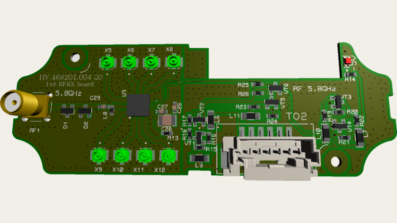
Receive board of a 5.8 GHz radar with eight RF connectors

Radar

Receive and transmit modules for a 5.8 GHz radar

Multilayer boards with an RF front end, a dedicated connector per channel, and power routed well clear of the sensitive section. Fabricated and assembled; the image is from the project’s 3D model.

5.8 GHz1×8 RFRX · 4×1 RFTX
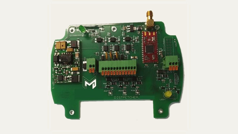
Assembled supervisory node board with a radio module and a multi-pin terminal block

Telemetry

Supervisory data acquisition node

An assembled, working board: a switching power supply, a bank of measurement inputs on a terminal block, a radio module with an antenna connector, and a separate service port for on-site commissioning.

Builtassembled and running, not a render
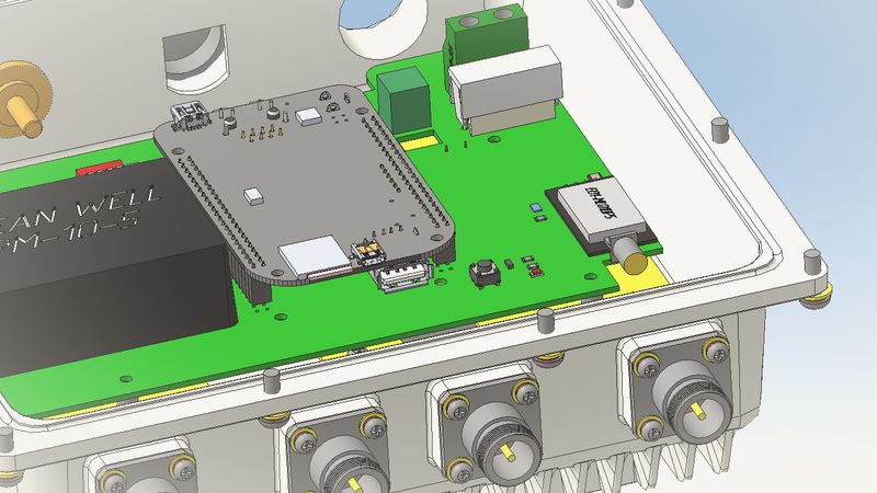
3D model of an industrial gateway in a sealed enclosure with cable glands

Industrial IoT

Warehouse gateway in a sealed enclosure

Board, power module, and compute unit share one sealed enclosure with cable glands for the external lines. The layout was verified in a 3D model before boards were ordered, so the lid closed on the first try.

Sealed enclosure3D fit check before fabrication
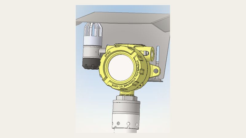
3D model of an explosion-proof gas detector with a sun shield

Process safety

Gas detector in an explosion-proof housing

Electronics designed around an existing explosion-proof housing: mounting points, entries, and the sun shield were fixed by the mechanical design, and the board was laid out to fit them, not the other way round.

Exbuilt to an Ex housing

Photo archive

Photographs from the work, unretouched

These are not stock images but working project material: assembled boards, panels from the fab, 3D models, and layout editor screens. Worth a look before a call, so the level of execution is visible instead of claimed.

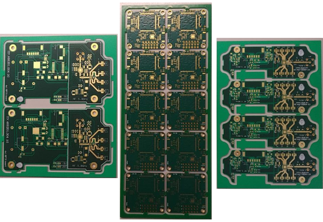
Several boards from one product family side by side
Board family of one productBase board, RF section, and power board in one project
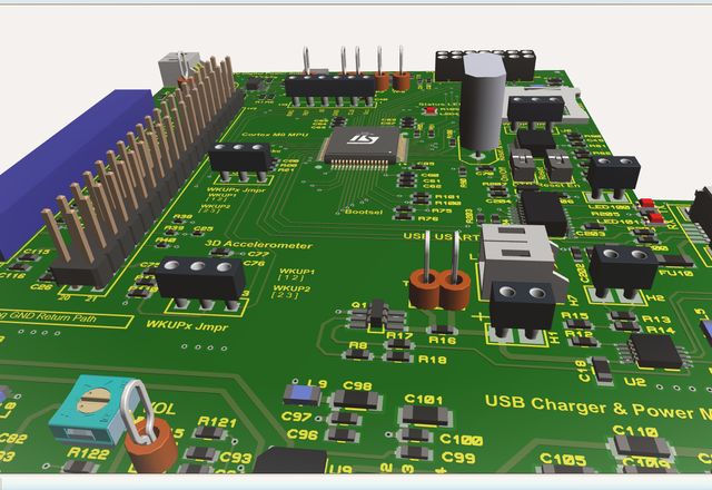
3D model of a board with processor, connectors, and power circuits
Processor and power boardAssembly checked in a 3D model before ordering
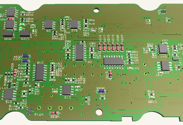
3D model of a long instrument-block board with dense assembly
Instrument blockDense assembly along the full length of the housing
3D model of a power supply board with large capacitors and connectors
Device power boardPower section routed clear of the signal section
3D model of a controller in an industrial enclosure with terminal blocks and cable entries
Controller in enclosureTerminal blocks, cable glands, and a clear lid in assembly
Stack of round boards with a battery cell inside a cylindrical housing
Industrial sensorStack-up for a cylindrical housing with its own power source
Multilayer board layout in the editor: power planes, traces, and vias

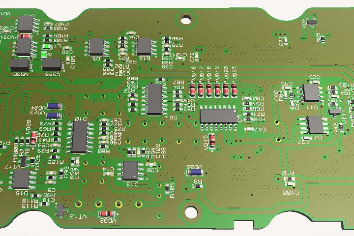
Before a board becomes an instrument it exists in full exactly like this: layer by layer, trace by trace.

Try it yourself

Flashing takes a second. Everything before it takes months

Press and hold the button. This is the moment all the preceding work is for: registers land, peripherals answer, the device comes alive. Let go early and the progress unwinds, exactly as it does on a real bench.

Ready to program

CLOCKClock168 MHz
POWERCore rail1.20 V
PERIPHPeripheralsSPI · I2C · UART
RADIORadio link−97 dBm
APPMain looprunning

Ways to work

Three ways to start, none of which needs the whole budget up front

Cost follows the difficulty of the blocks, not the size of the contract. You can start with a single short milestone and decide what comes next from its result. A firm quote follows the requirements milestone, once the risks are known, not on day one by email.

Audit

from 1 weekfixed price

  • Review of the existing schematic and layout
  • Firmware read-through and bench measurements
  • Prioritized defect list
  • A straight verdict: repair or respin
Order an audit

Turnkey development

8–16 weeksmilestone-based payment

  • Requirements, breadboard, board, firmware, production
  • A deliverable at the end of every milestone
  • All sources and rights stay with the client
  • First-revision fixes at no extra charge
Start a project

Engineer on retainer

monthlypart-time

  • Reinforcement for your team on a hard block
  • RF section, FPGA, drivers
  • Work in your repository, under your rules
  • Exit with nothing left dangling
Discuss availability
Which engagement fits
EngagementDurationBudgetWhat you receive
Audit of an existing boardfrom 1 weekfixed price, quoted up frontPrioritized defect list and a repair-or-respin verdict
IoT device, turnkey8–16 weeks$5,000–25,000 for a typical deviceSchematic, PCB, firmware, radio link, pilot units, full sources
Engineer on retainermonthlymonthly rate, part-timeWork inside your repository on one hard block

FAQ

What clients ask before signing

Direct answers to the seven questions that usually decide a project. If an answer does not suit you, better to know now than in the third month of work.

Who owns the source files and the IP?

All rights transfer to the client once the milestone is paid. You receive the firmware source, the KiCad project, the schematic, the BOM, and the manufacturing files. No locked binaries and no vendor lock-in: any other engineer can pick the package up and continue.

What does turnkey development of a device cost?

A typical connected device — board, firmware, and radio — falls between $5,000 and $25,000. Cost follows the difficulty of the blocks, not the page count of the contract. A simple microcontroller sensor with a radio link usually fits one short development cycle; a radar or FPGA product takes several. A firm estimate follows the first milestone, where requirements and architecture are locked.

How long does board and firmware development take?

A typical cycle from agreed requirements to a working prototype runs eight to sixteen weeks. A breadboard on evaluation kits comes earlier, usually in week two or three, to retire the risky blocks before a custom board is ordered.

What happens if the board does not work?

Risky blocks are proven on a breadboard before the board is released, and first-revision errors are fixed at no extra engineering charge. You pay only for the fab to rerun the boards. Defects are reported straight away instead of being papered over with firmware workarounds.

Will you take over someone else’s board or an unfinished project?

Yes, that is a common job. It starts with an audit: schematic, layout, firmware, and bench measurements on real hardware, followed by a prioritized defect list with the cost of each fix. Sometimes the honest verdict is that respinning the board beats repairing it.

Do you also do plant automation, not only boards?

Yes. Beyond boards and firmware, the work covers cell automation on industrial PLCs, supervisory control and SCADA, robotics, and machine vision with recognition. These systems are already running in production plants, commissioning included.

Do you sign an NDA?

Yes, the NDA is signed before any material changes hands and before the first technical call. Projects are never published without the client’s written consent, and no one else’s work is reused.

3D portfolio

Spin our work.
Right now, with your mouse.

On the right — a real 3D model of an industrial sensor we built end to end: board, firmware, enclosure. Five more devices in the gallery.

Open 3D gallery →
↻ model is rotating — take control

Get started

Describe the job in three sentences

A reply comes within one business day: an estimate, or a referral if the job is outside our scope. The first call is free, and the NDA is signed before it.

A reply within one business day
Inquiry received. A reply will reach the address you gave within one business day.
The message could not be sent. Please write to info@mpv-lab.com.